

USB-C PD/QC/AFC Trigger Module - Fixed 5V/9V/12V/15V/20V Decoy Board
USB-C PD/QC/AFC Trigger Module - Fixed 5V/9V/12V/15V/20V Decoy Board
In stock
Couldn't load pickup availability
Overview
Turn any USB-C fast charger into a fixed-voltage bench or project supply. This decoy (trigger) module negotiates with a PD, QC or AFC charger over the CC lines and locks the output to whichever voltage you select on the DIP switch: 5 V, 9 V, 12 V, 15 V or 20 V. No firmware, no configuration software, no extra components. Set the switches, plug in, verify with a multimeter, and wire it into your project.
It is a genuinely useful little board if you have a drawer full of laptop and phone chargers and keep needing a clean 12 V or 20 V rail for a router, an amplifier, a solar charge controller input, or a bench test rig.
Key features
- Broad protocol support: USB PD 2.0 and PD 3.0, Qualcomm QC 2.0 and QC 3.0, and Samsung AFC. Works with the vast majority of modern USB-C chargers and power banks.
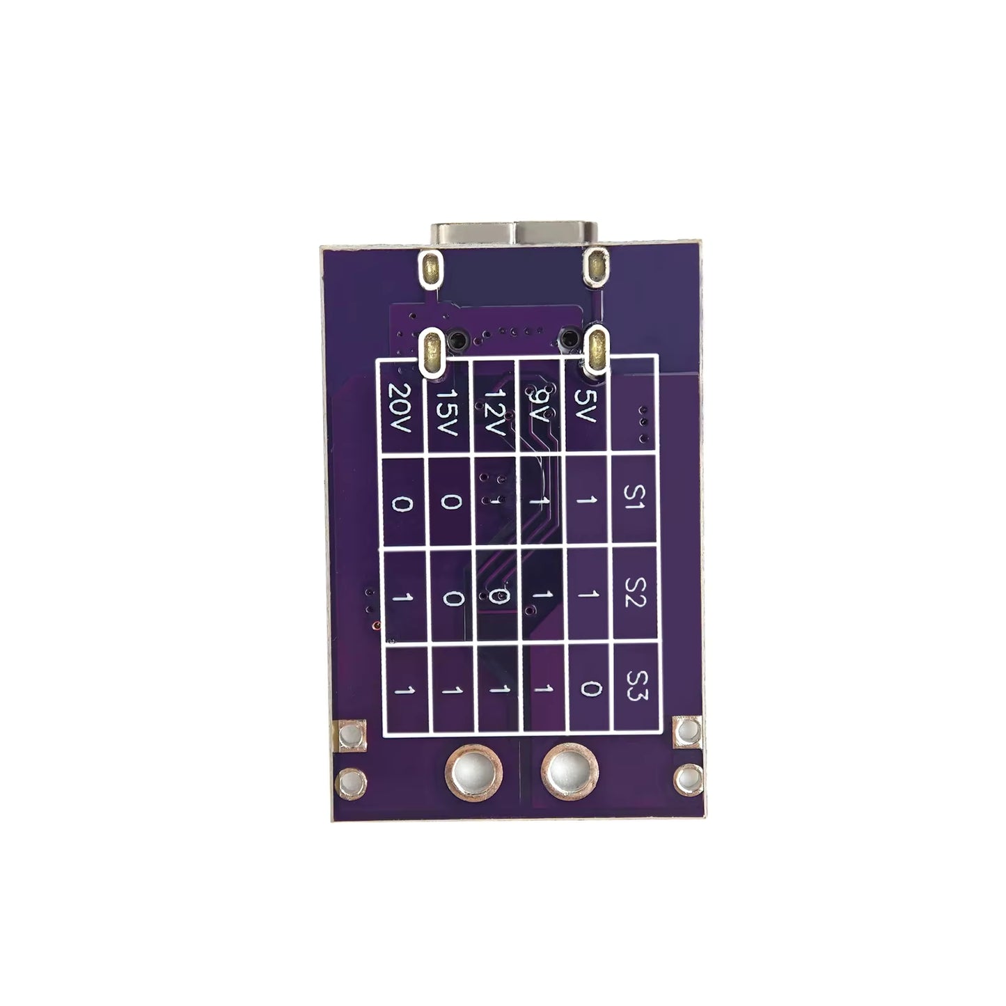
- Five fixed output voltages: 5 V, 9 V, 12 V, 15 V and 20 V, selected with the on-board 3-position DIP switch (S1, S2, S3).
- High power capable: current is limited only by your charger and cable, so a 100 W supply can deliver the full 20 V at 5 A through the module.
- No programming required: the switch combination table is silkscreened on the reverse of the board.
- Compact: roughly 35 x 20 mm, small enough to hide inside a 3D printed enclosure or an existing chassis.
- Flexible output connection: heavy solder pads with plated through holes at standard terminal block pitch, plus a pair of 2.54 mm holes on each side for header pins. Fit a screw terminal, solder wires straight on, or drop it onto your own carrier board.
- On-board power LED for an at-a-glance confirmation that the module is live.
Specifications
| Supported protocols | USB PD 2.0 / PD 3.0, QC 2.0 / QC 3.0, AFC |
|---|---|
| Input connector | USB Type-C female |
| Output voltages | 5 V, 9 V, 12 V, 15 V, 20 V (fixed, DIP selectable) |
| Voltage selection | 3-position DIP switch (S1, S2, S3), combination table printed on the underside of the board |
| Maximum output | Determined by the connected charger, up to 20 V / 5 A (100 W) with a suitable supply and e-marked cable |
| Voltage accuracy | Typically within 5% of the requested rail |
| Output connection | V+ and GND solder pads with plated through holes at terminal block pitch, plus two additional 2.54 mm pitch holes per side for header pins |
| Trigger IC | PAK02A |
| Logic rail | HT7550-1 5 V LDO |
| Indicator | On-board power LED |
| Dimensions | Approx. 35 x 20 mm |
How it works
USB-C chargers do not simply output whatever you ask for. They sit at 5 V until a device requests something higher over the configuration channel. This module performs that request on your behalf and then holds it, so the charger keeps supplying the selected voltage indefinitely.
Negotiation is handled by a PAK02A trigger IC, with an HT7550-1 linear regulator dropping the output rail down to a stable 5 V for the chip's own logic supply. That is the entire signal path, so nothing on the board sits between the charger and your load.
Because it is a trigger rather than a converter, it does not boost, buck or regulate. The output is whatever the charger provides, passed straight through. That means very high efficiency and no switching noise added by the module, but it also means the charger must genuinely support the voltage you select.
Quick start
- Set the DIP switch to the voltage you want, using the table printed on the back of the board.
- Plug in the charger with a USB-C cable. For anything above 60 W, use an e-marked (5 A rated) cable.
- Measure the output pads with a multimeter and confirm the voltage is what you expect.
- Connect your load only after that measurement checks out.
Typical applications
- Powering 12 V routers, switches, LED strips, fans and amplifiers from a USB-C charger or power bank
- Running or bench-testing laptops and notebooks that accept 15 V or 20 V
- Feeding a solar MPPT or charge controller input at a known fixed voltage
- Portable and off-grid setups where USB-C power banks are the only supply available
- Electronics bench work, phone and tablet repair, and general prototyping
- Replacing a lost or failed proprietary wall wart with a modern USB-C charger
What to be aware of
- Fixed voltages only. There is no continuously adjustable or step-by-step output.
- No voltage display. There is a power LED, but no readout of the selected rail. A multimeter is required for verification.
- No step-up. The charger must support the voltage you select. Requesting 20 V from a 30 W charger will simply leave you at a lower rail.
- No current limiting or output protection. Fusing and protection downstream is your responsibility, as with any bare module.
- Huawei SCP and OPPO VOOC are not supported. PD, QC and AFC only.
Frequently asked questions
I set 9 V but I am only measuring 5 V. Why?
Three usual causes: the charger does not actually support 9 V, the DIP switch is not making solid contact, or the switch combination is not one of the valid entries in the table. Re-check the table, give the switches a firm toggle, and measure again.
Can I power a laptop with it?
Yes, provided the laptop accepts 20 V or less on its input and the charger can supply enough current. A 20 V / 3 A (60 W) charger will run most thin-and-light machines.
I selected 20 V but only measured 5 V.
Your charger almost certainly does not offer a 20 V PDO. In practice 20 V generally requires a 65 W or larger PD charger.
Does it show the output voltage?
No. The on-board LED only confirms that the board has power, it does not indicate which voltage has been negotiated. Always measure before connecting a load.
Does it support Huawei SCP or OPPO VOOC?
No. It handles PD, QC and AFC only.
In the box
- 1 x PD/QC/AFC fast charge decoy trigger module
USB-C cable, charger, screw terminal block and header pins are not included.
Dr Gough Lui's excellent testing & review: https://goughlui.com/2026/08/02/tested-usb-pwr-pak02a-based-usb-c-pd-legacy-trigger-decoy-board/